Transaxle
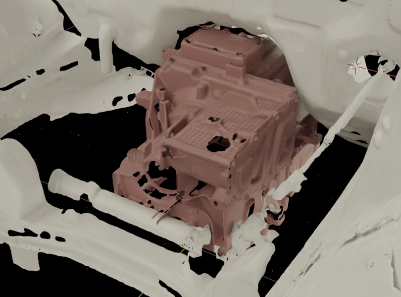
After several months of 3D scanning, taking measurements, and rearranging models in CAD, I determined that the motor had to stay in its original housing, and it had to live at the front of the transmission tunnel.
The original transaxle collides with the steering rack in this configuration. One workaround could be to relocate the steering rack forward. This is a common modification for drift cars with modified knuckles, but it would severely impact Ackerman steering geometry in an otherwise unmodified steering setup. The steering shafts could have been modified to maintain the original pivot point positions after relocating the rack, but I did not trust myself to perform this modification without causing the steering rack to bind or not operate reliably.
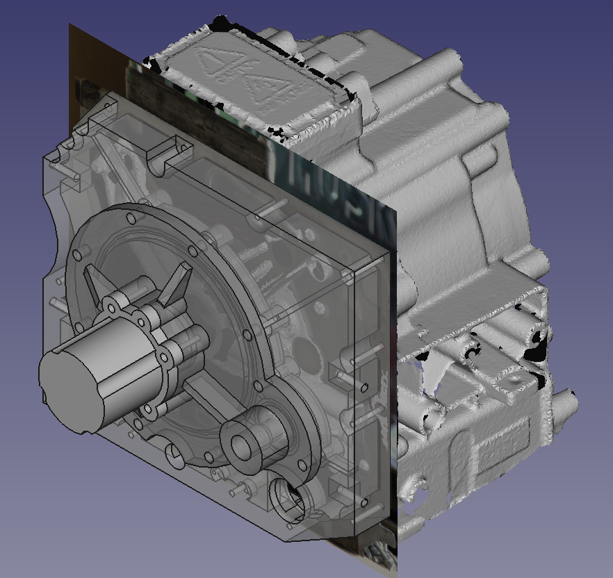
I decided to ditch the transaxle and replace it with a custom faceplate. The faceplate was designed in FreeCAD using an image and a 3D model as a reference. To ensure that the reference image scaling was accurate, the original motor/transaxle gasket was scanned in an enterprise printer with a large scan bed.
The custom faceplate consists of three parts. The larger two parts are designed to be machined from 1.5" thick aluminum plate. Standard oil resistant O-rings are used to seal all interfaces. 10AN fittings are used for the oil pump inlet and outlet, and the original electrical connector is used to connect the vehicle harness to the motor’s hall effect sensors.
After spending a week designing the custom faceplate, I decided to try chopping up the transaxle to see if it would be possible to just use the inner pieces of that instead. Reusing the original transaxle would save ~$700 in raw materials and other components over building the custom faceplate.
After becoming intimately familiar with the grinder for a day…
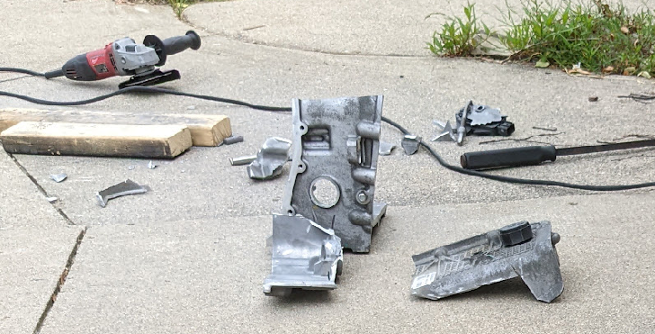
…the transaxle core was liberated.
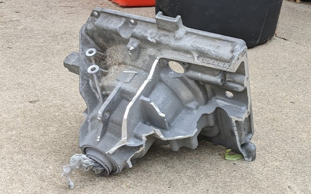
There were many openings in the core of the transaxle. One hole provided clearance, another secured a cable tie, and various other holes were added for components to pass through. Only a few holes in the assembly appear to be designed for oil passage. Most of these holes were quick to plug up with some aluminum filler rod, though welding 1/4" aluminum on a 120V, 15A circuit was a challenge. The breaker for this circuit had to be reset about 30 times throughout the welding process. There are two separate 120V circuits in the garage, and those circuits will be joined together for future aluminum welding projects.
Some 1/4" 6061 bar stock was used to plug a hole with an opening for an oil drain port. This drain port will feed into the oil pump, which used to be located in the sump of the transaxle that is now removed.
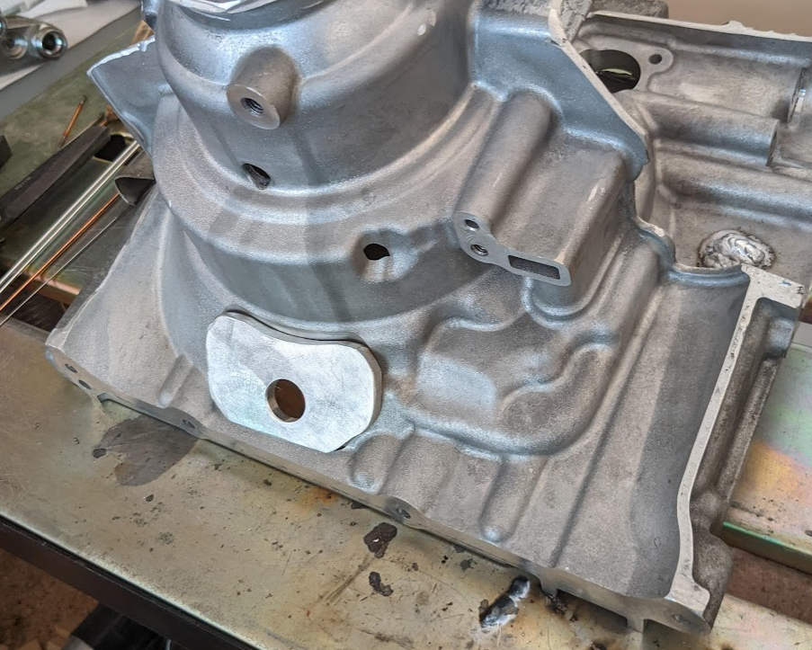
The cast aluminum was relatively easy to weld despite the breaker constantly flipping. The aluminum was not too porous, and the welding surfaces were prepped by using the TIG torch without filler to drive air pockets up to the surface.
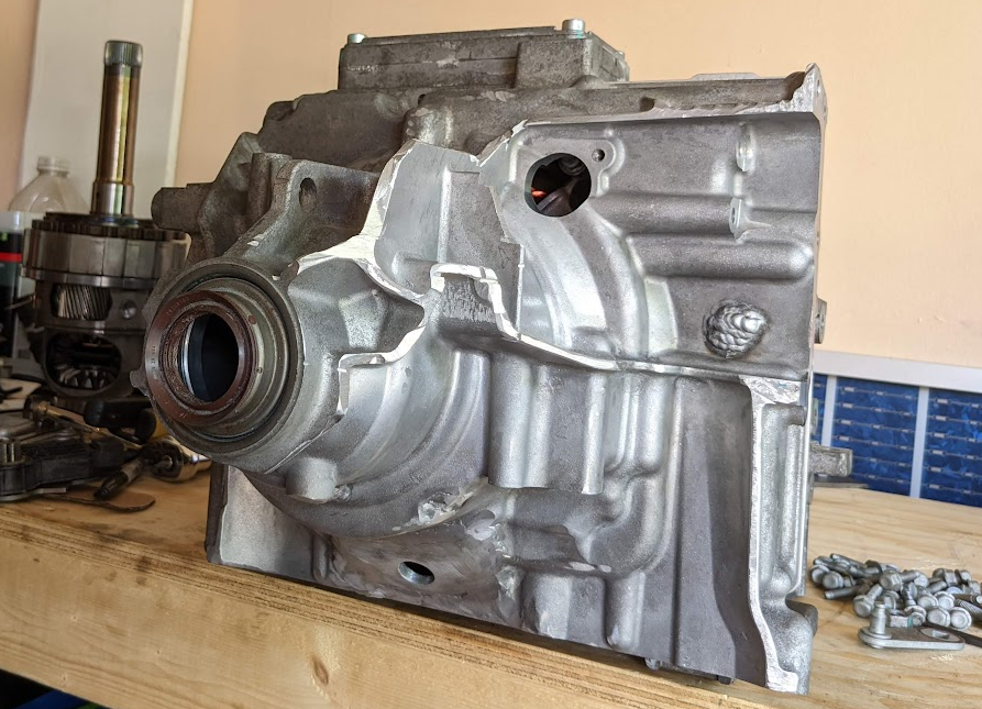
The remaining opening will be modified to fit a bulkhead connector for the six hall effect sensor wires. By keeping the original transaxle core, I will also be able to re-use the existing thrust bearing surfaces to support the driveshaft.
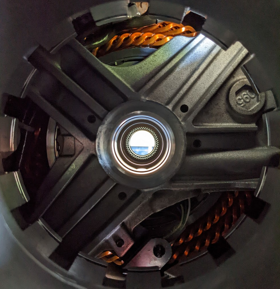
Here’s a bonus shot of the motor from the driveshaft hole in the transaxle.