3D Scanners
This project is complex enough to warrant buying a 3D scanner to aide in component layout, but almost all 3D scanners with decent resolution and accuracy are prohibitively expensive for a hobbyist.
Hardware
Two scanners were used for this project: a Revopoint POP and a custom scanner based on an RPLidar A1M8.
Revopoint POP
Revopoint had recently released the POP 3D scanner, which was reasonably priced at around $650. Creality also had a competing product, but the POP was more refined. The POP has 0.1mm accuracy. I purchased the POP a few months before the POP2 was announced, which has 0.05mm accuracy and a gyroscope to improve scan accuracy over larger targets.
The Revopoint POP is great for creating high resolution scans of small to medium sized objects, but it lacks the precision needed to scan an entire vehicle chassis. Revopoint software will automatically distort the scanned model to better align roughly overlapping sections. This distortion is usually minimal and welcome on smaller models, but it becomes inaccurate on larger models such as a vehicle chassis.
RPLidar Based Scanner
A second scanner was needed for modelling the underbody of the car. 2D scanning lidar sensors with reasonable accuracy are inexpensive. The RPLidar A1M8 is $99 with an angular resolution of 1 degree and a range resolution of 1% of distance. I planned to create a 3D scanner from this by mounting the lidar sensor to the powered lazy suzan that came with the Revopoint POP. A similar project was open sourced which showed good potential for this idea.
The end result was a hacky looking and not very rigid scanner.
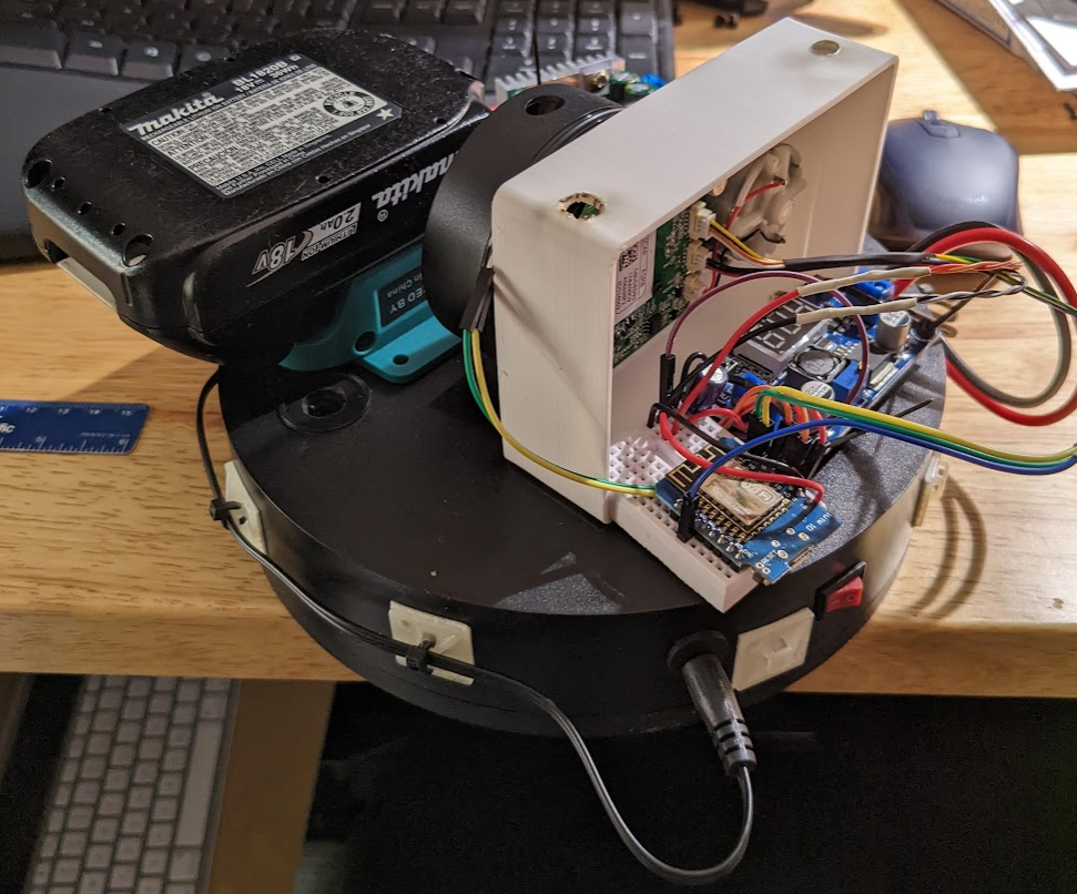
An ESP8266 is used to control the lazy suzan, receive data from the RPLidar, and transmit the RPLidar data along with the azimuth angle to a host over wifi.
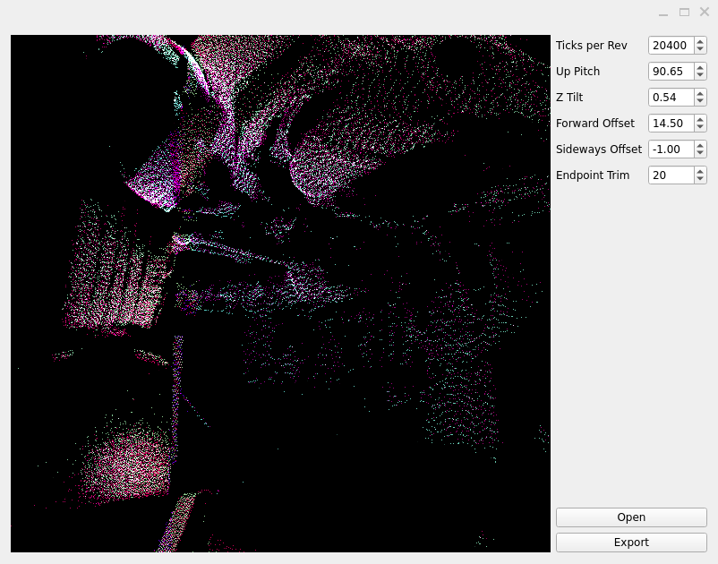
The poor rigidity of the structure is roughly made up for in software. The rplidar_area_scanner repo contains a script to adjust for various angles and offsets as a post processing step, as shown below.
Software
3 different pieces of software are used to post process 3D scans:
-
MeshLab is used for point cloud cleanup, simplification, and meshing.
-
CloudCompare is used to merge point clouds together.
-
Revopoint software (HandyScan/HandyStudio) is used to mesh point clouds collected from the Revopoint POP.
-
Revopoint software typically creates smoother meshes at the expense of losing details that don’t have many points.
-
This software also supports mesh merging, but the merging process may distort the meshes.
-
Meshing Process
There are multiple ways to convert point clouds to meshes, but the following method produces good quality meshes while maintaining as much of the original scan as possible. The meshing process in Revopoint software tends to ignore portions of the point cloud that are more isolated from the rest of the point cloud.
-
Open the mesh in Meshlab, then use the Select Vertices and Delete Selected Vertices tools to clean up the mesh.
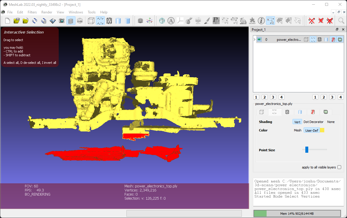 Figure 3. Manual mesh cleanup
 -
Simplify the mesh with .
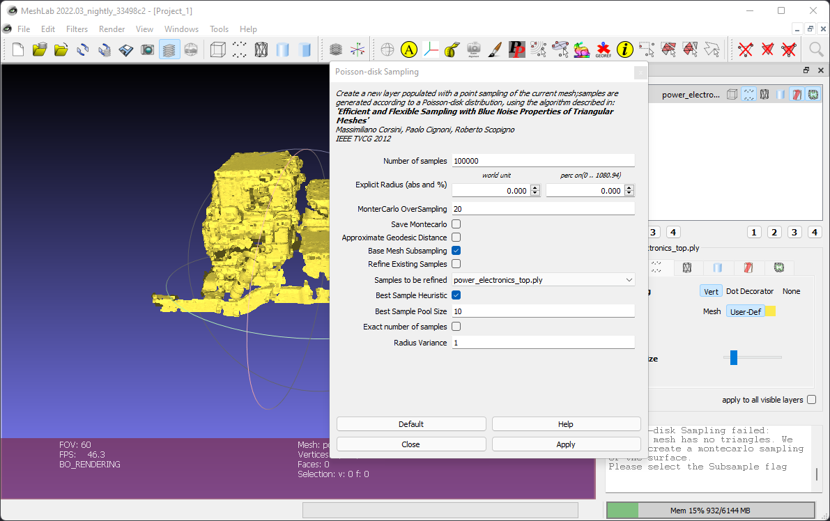 Figure 4. Vertex sampling
-
Base Mesh Subsamplingmust be selected for vertex-only data. -
Number of samplesis a balance between resulting mesh quality and size. For more detailed meshes, 600,000 is a reasonable starting point.
-
-
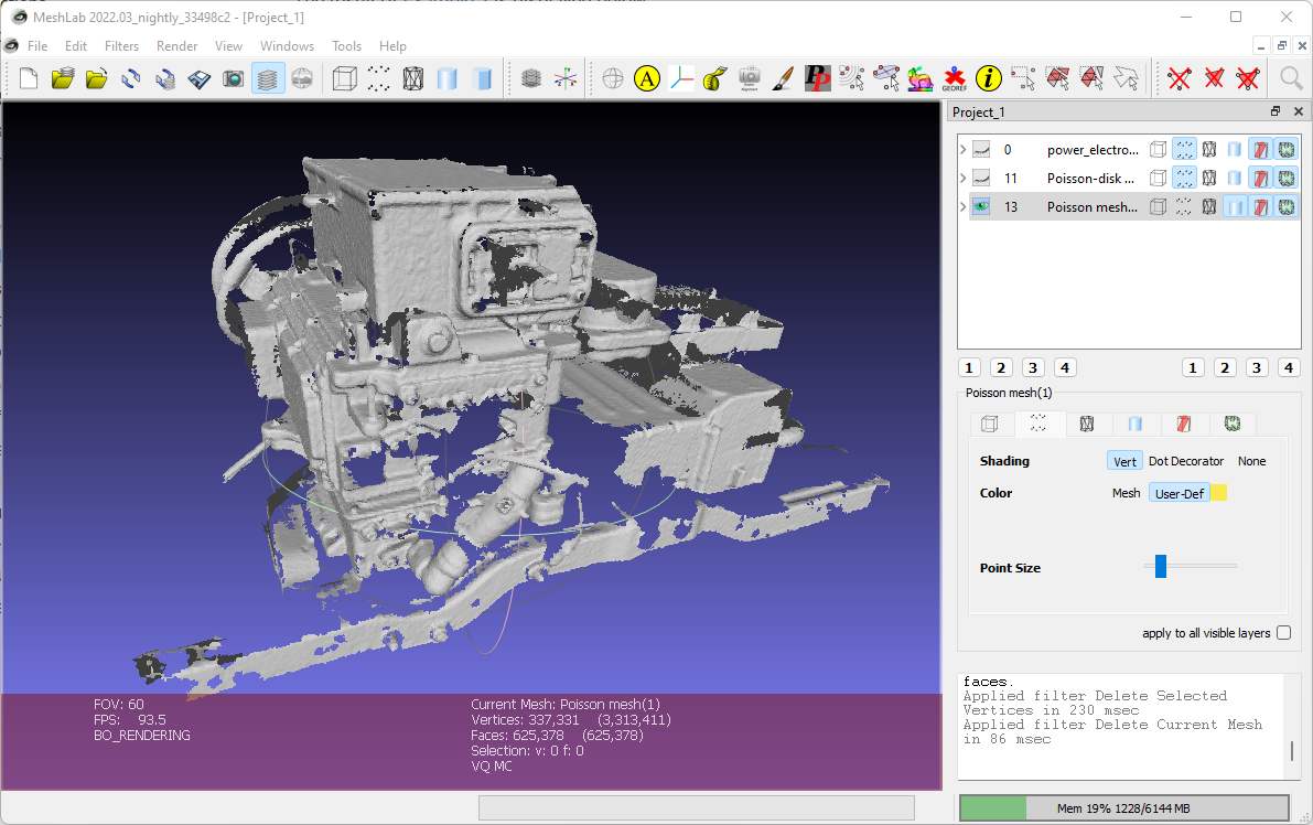
With the simplified point cloud selected, generate an initial mesh with .
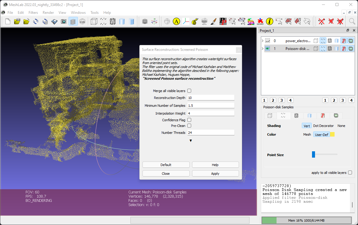 Figure 5. Surface reconstruction
-
Higher reconstruction depth will improve the amount of detail in the mesh at the cost of compute time. Too high of a reconstruction depth will make the mesh less smooth, especially if the point cloud is not very dense.
-
-
The Screened Poisson reconstruction technique leaves excess mesh that must be trimmed away. To trim the unwanted vertices in the mesh, first use to calculate the distances from the Poisson mesh vertices to the original point cloud vertices.
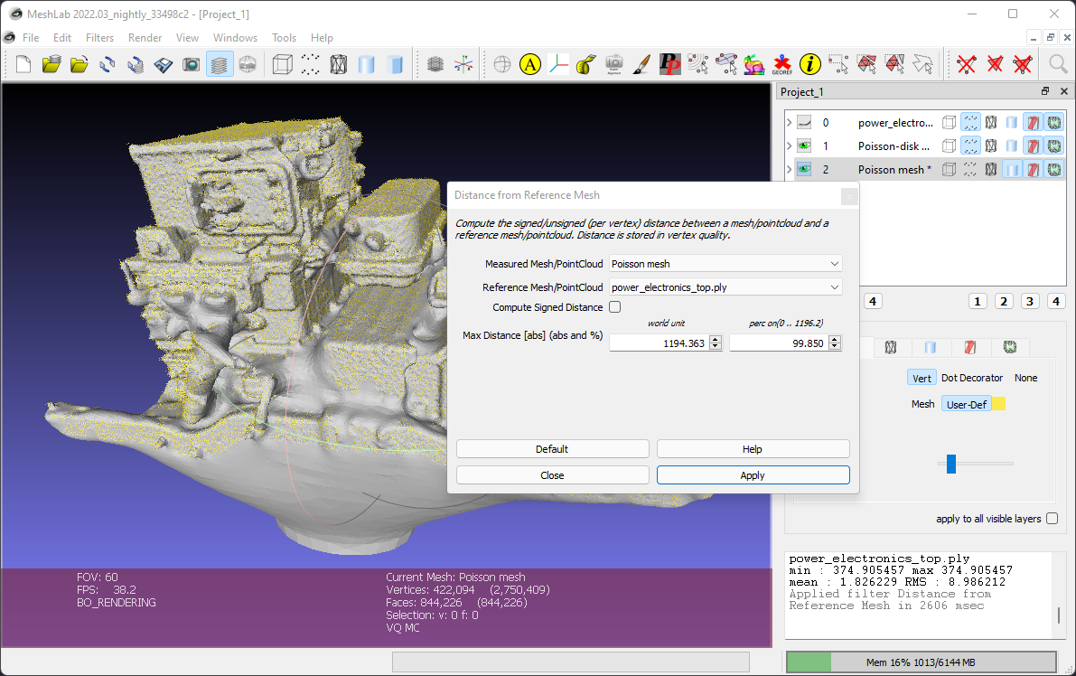 Figure 6. Mesh distance from original point cloud calculation
-
Uncheck
Compute Signed Distance. -
The distance information is stored as vertex quality data in the Poisson mesh.
-
-
Select vertices that are not in close proximity to the reference mesh by using , where
Qualityis distance in mm.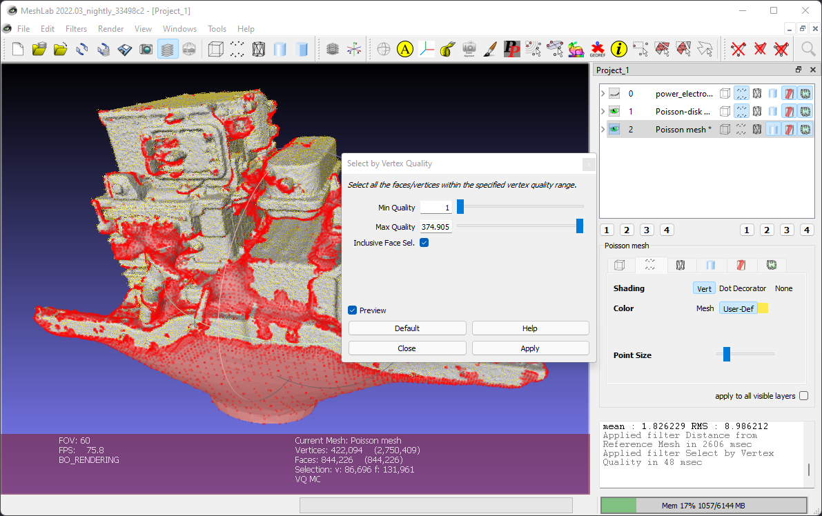 Figure 7. Mesh vertex selection by quality
-
Select a
Min Qualityvalue that balances accuracy and appearance for your application. The minimum distance will vary based on point density of the original point cloud.
-
-
Use the Delete Selected Vertices tool to remove the unwanted vertices.
The final product is a reasonably smooth and lightweight mesh with high accuracy.