Front Battery Box
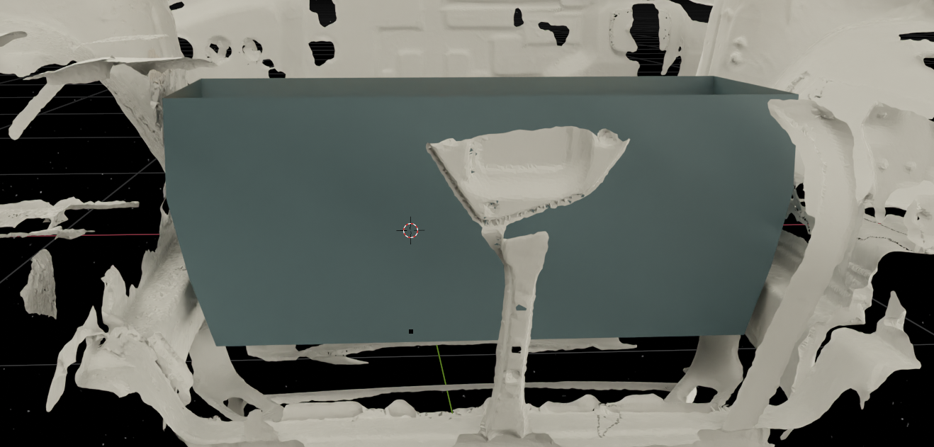
The front battery box was modelled in blender around the 3D scanned battery cells. A cheap sheet metal brake was used to fabricate the basic assembly per the model’s dimensions.
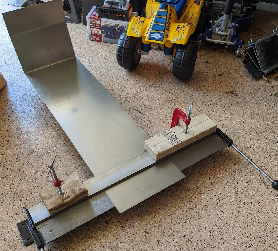
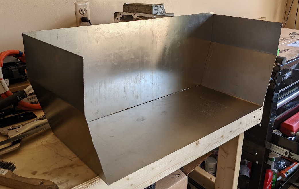
It turns out the 3D model did not include some brackets that shielded the coolant ports on the battery cells… This was resolved with some more brake action.
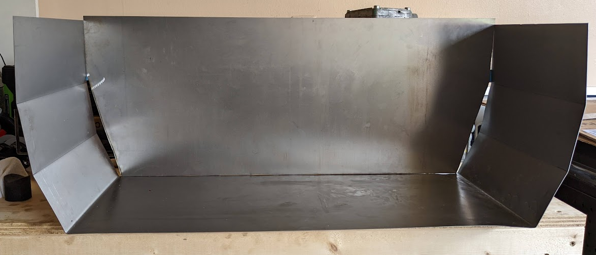
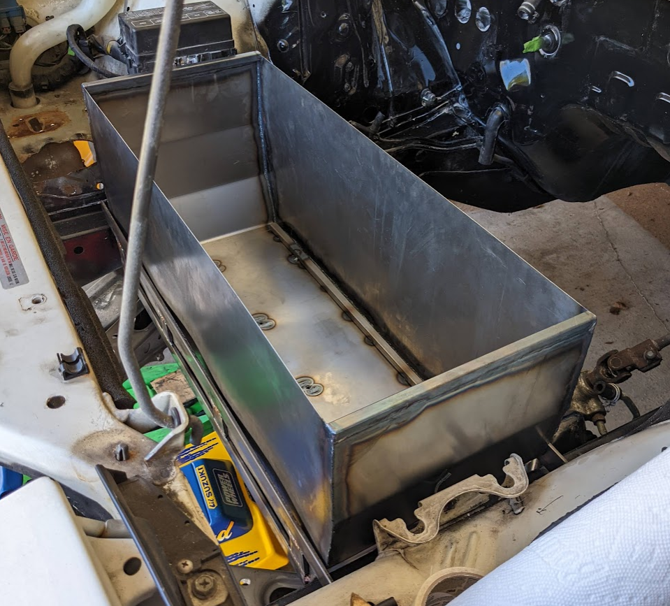
The box was placed in the engine bay to check fitment. The additional bends require the box to be slightly higher than original expected.
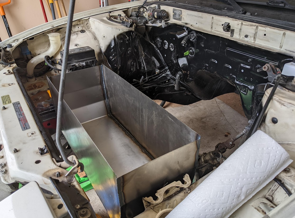
The CAD model was updated with the new battery box design and the fitment was confirmed to match the physical measurements.
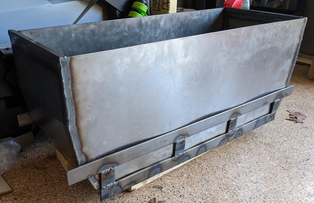
Front Battery Box Structural Members
Square tubes and bars were used to add structural support to the front battery box. These structural components were welded directly to the sheet metal assembly.
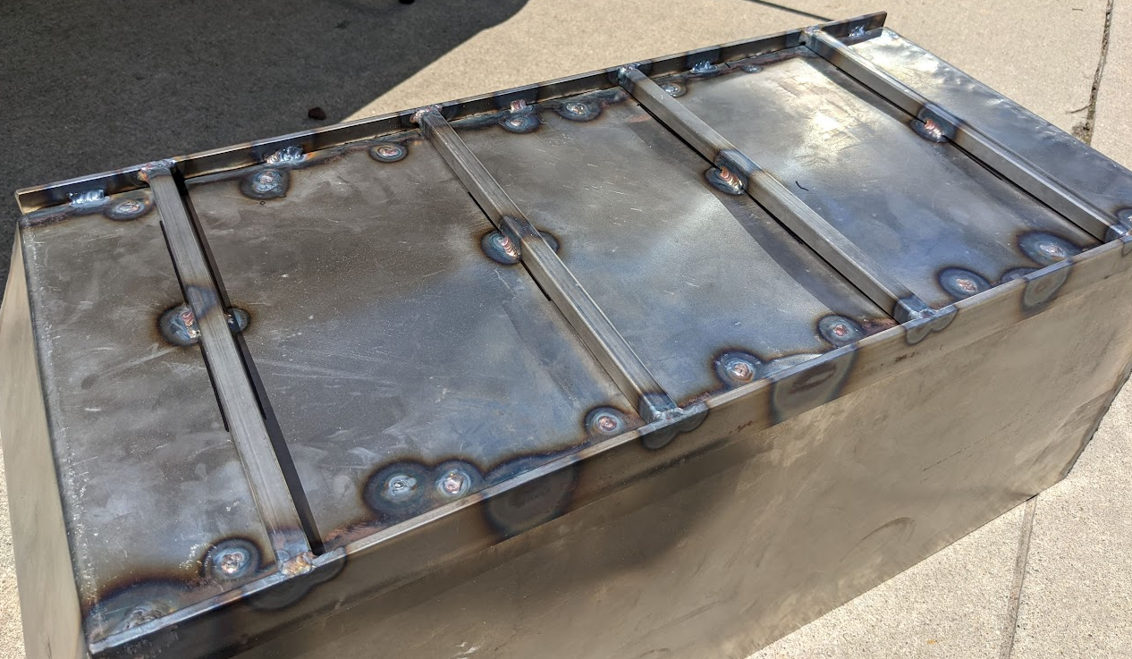
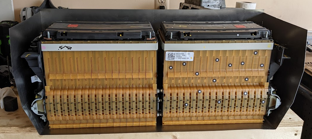
Unfortunately, this led to quite a lot of warping which needs to be corrected. The battery cells sit flat on the bottom of the box.
Steel bar was used to create a mounting structure. Each butt weld started with heavy chamfers to ensure at least 50% penetration, and stainless steel filler was added on top of the weld surface to improve strength.
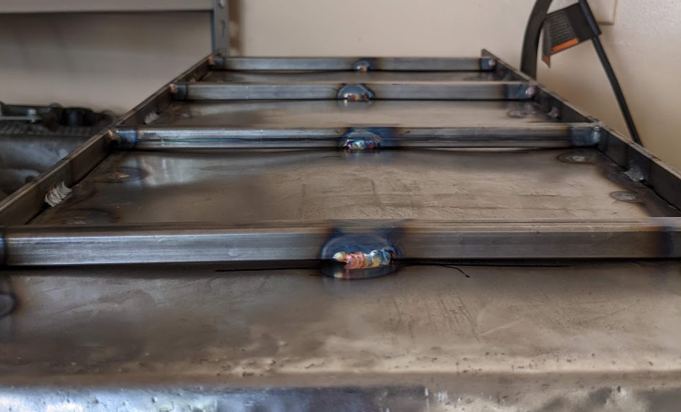
Here is the battery tray in the engine bay:
Warpage Correction
After welding the structural components to the sheet steel, it was time to un-weld them. After some time with the angle grinder, then the drill, then the angle grinder, then the 3 lb sledge hammer, the structure components finally lost grip.
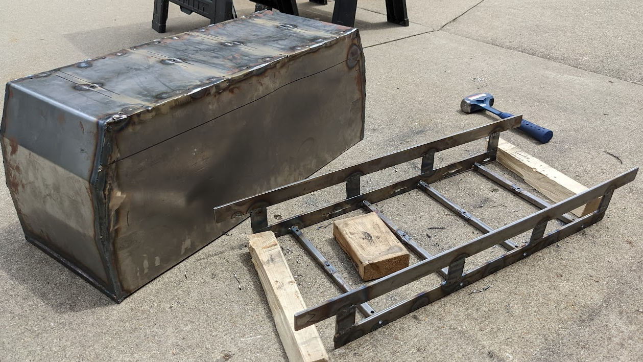
Both the structural piece and the sheet steel had significant twists. The structural component was corrected on the welding table with shims and clamps. The TIG welding torch was used to heat up the cross members while slowly tightening the clamps to eliminate all the twist.
The base of the sheet metal box was shrunk using a propane torch and a hammer. The process was repeated a few times to achieve an acceptable level of flatness.
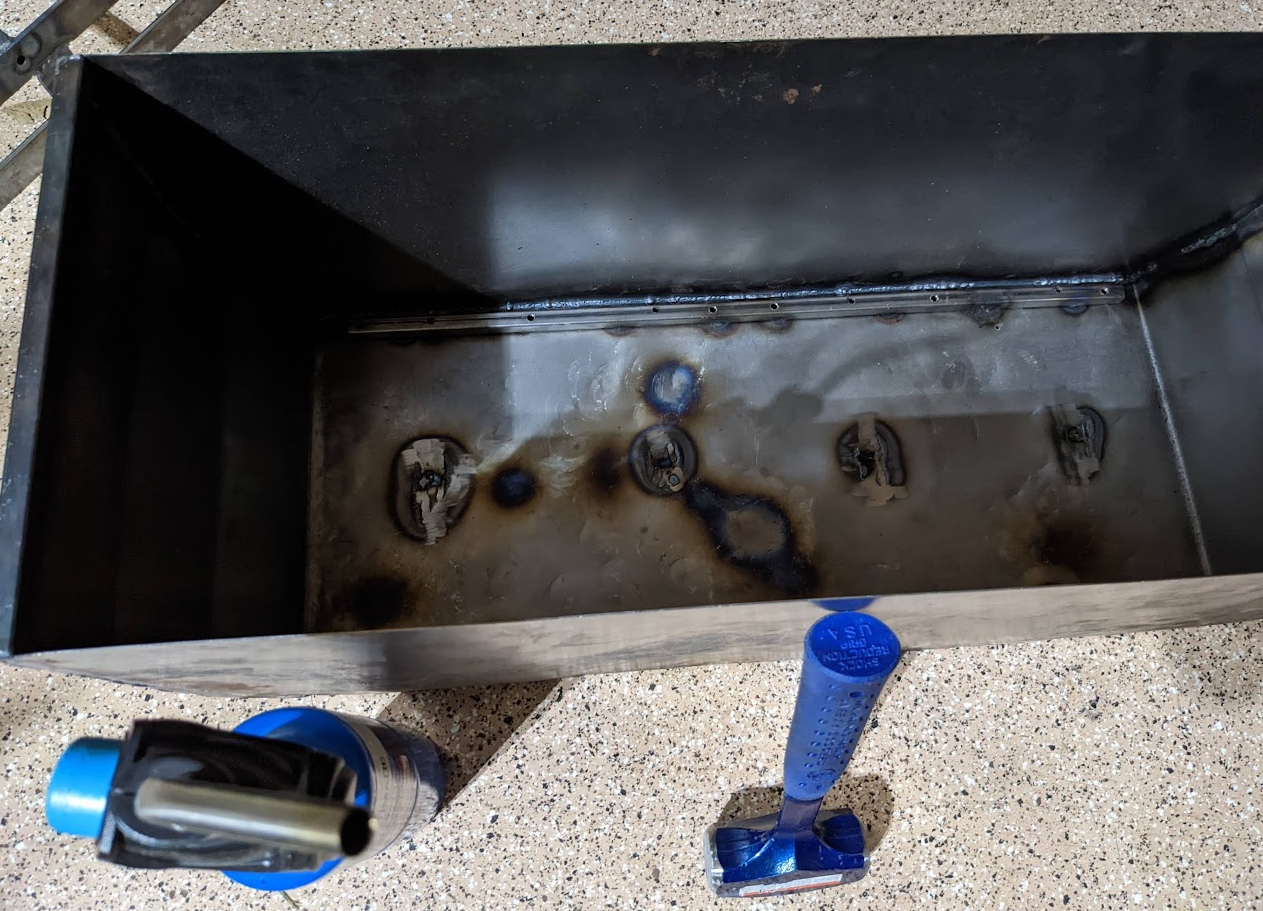
The sheet metal was fastened to the structural component with eight M8 bolts.
