Component Layout
Determining where to place the components was a major challenge for this project. There are multiple options for component placement, but I ended up choosing The Partially Redesigned Motor Housing.
The Reverse Spark
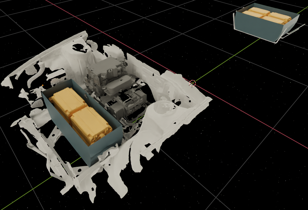
The Chevy Spark has the motor, electronics, and cooling in the front of the car, and the battery pack is a single unit located at the rear of the car. The "Reverse Spark" layout is the reverse of this.
The battery pack would be located in the engine bay, but one cell would be located in the transmission tunnel to make room for the steering column.
The motor and transaxle would take the place of the existing differential. The driveshafts would be aligned almost perfectly to the stock 240sx positions, but there were a few other problems:
-
There is no limited slip differential option for the transaxle.
-
GM used a differential that is typically found in low power (<150HP) motors mated to automatic transmissions. I was unable to get a response from a large differential shop about building an LSD for this transaxle.
-
-
The motor/transaxle housing would protrude into the rear seat area by a few inches.
-
The assembly is slightly wider than the 240sx differential, and suspension mounting points would need to be shifted slightly to get everything to fit.
Finally, the power electronics would also be situated below the trunk to be in close proximity to the motor, but they would protrude slightly into the trunk area. Smaller radiators could be used at the rear of the car, and the bumper could be replaced with a mesh to improve airflow through these radiators.
The Completely Redesigned Motor Housing
Once it was determined that the original differential needed to stay, there was really only one way to arrange the battery and power electronics such that everything fit in the chassis.
Battery Pack and Power Electronics
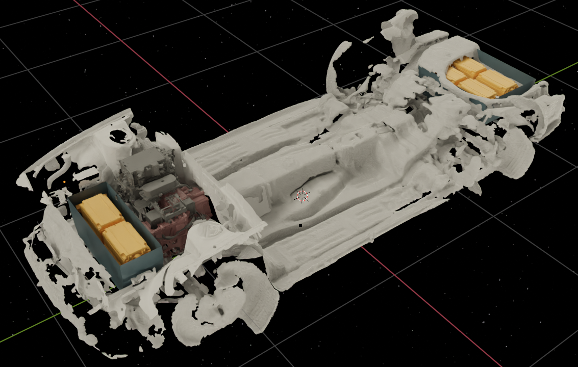
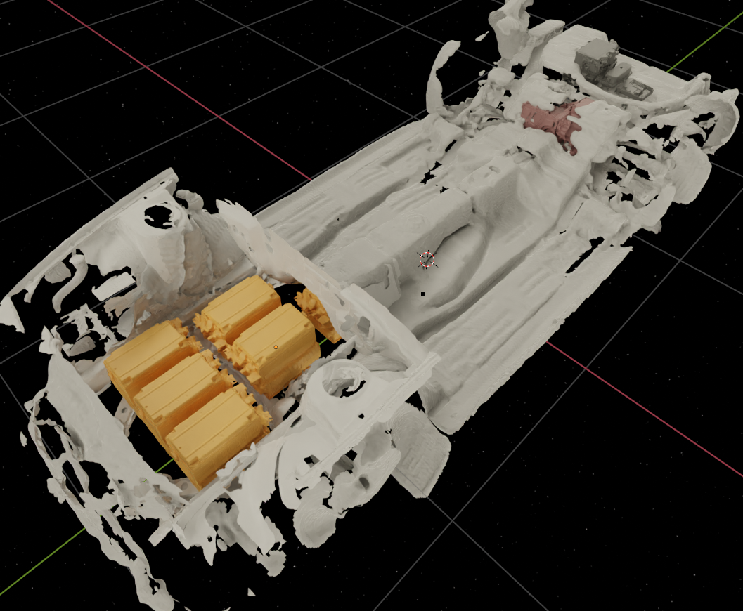
The battery pack would need to be split between the front and rear of the chassis, and the power electronics would be situated in the engine bay.
The front battery cells could not be located in the rear of the engine bay because they interfere with the steering column. When the batteries are in front of the power electronics, only two battery cells fit. If a third cell is added to the front pack, there would be no room for radiators.
With this layout, there is space beneath the power electronics to mount pumps, the AC compressor, and other components.
Motor
The motor stator and rotor are relatively compact, but the housing is bulky.
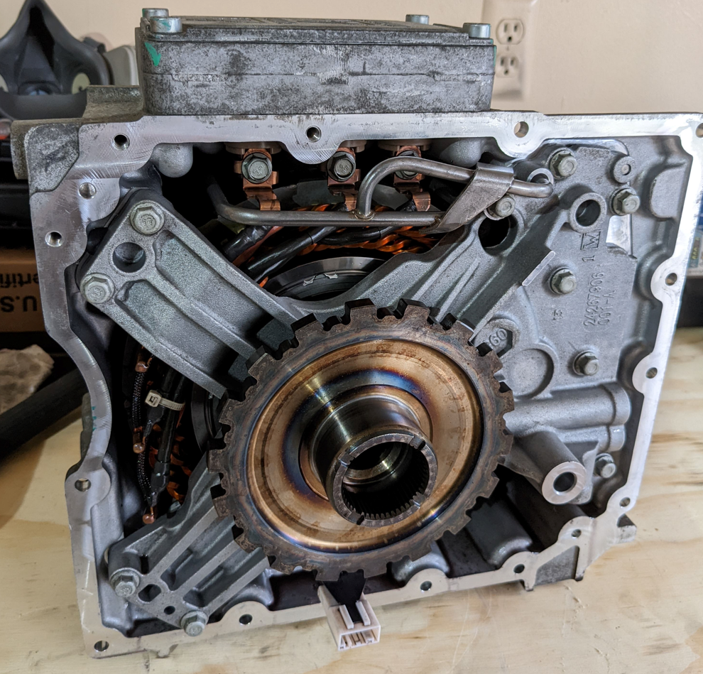
The stator is bolted to the rear of the housing with 4 long bolts, and the rotor is mounted on bearings on either side of the assembly.
In an ideal scenario, the motor housing would be replaced with a 10" ID aluminum pipe, and the end caps would be CNC machined to include the proper mounting structures and oil passages. This assembly would be able to be bolted directly into the transmission mount location, which is both rigid and centrally located in the chassis.
This custom motor housing would likely cost upwards of $1000 in materials alone, and it would require additional components such as an external oil pump.
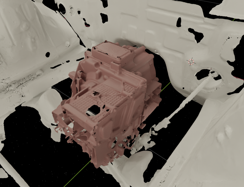
The Partially Redesigned Motor Housing
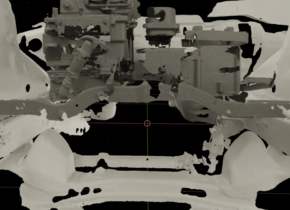
Instead of completely redesigning the motor housing, the front face could be replaced with a machined aluminum component or a welded structure. This motor assembly would be located at the front of the transmission tunnel where the square surface can protrude into the engine bay. The motor would be far enough back to not interfere with any of the components in the engine bay.
The welded structure option would be lower cost, but still require access to at least a manual mill for post processing the gasket surfaces.
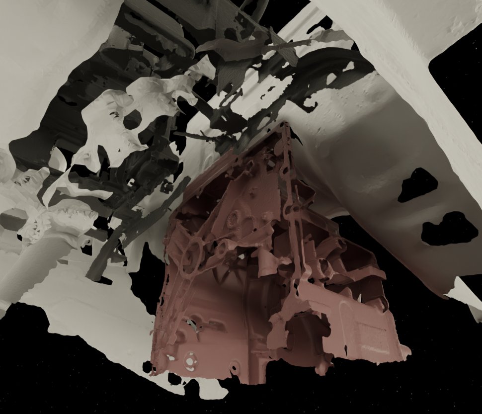
The Busy Engine Bay
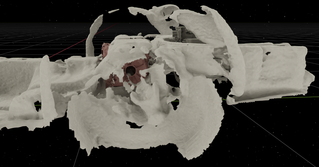
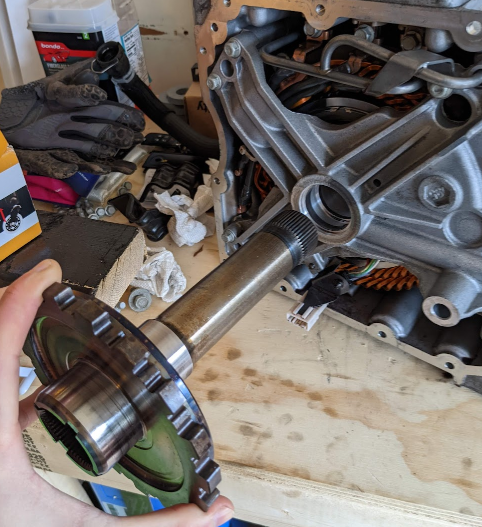
This option maintains the motor and transaxle with some modifications to bypass the gearing in the differential and send all the power directly out the rear of the motor. This can be achieved by modifying the hollow motor/transaxle coupler and the axle that normally passes through it.
This motor/transaxle assembly would be located in the engine bay where the KA24E engine block was originally located in the stock 240sx. It is not possible to leave the motor partially inside of the transmission tunnel with the transaxle attached because the transaxle interferes with the steering rack.
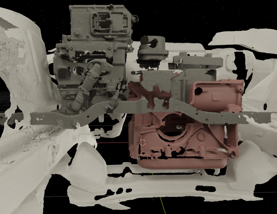
The power electronics would need to be rearranged for this layout, since the motor and transaxle are higher up in the engine bay. The power electronics stack vertically, which is optimal for the tall but narrow engine bay in the Spark. It is not feasible to unstack the electronics without completely remaking most of the high voltage wire assemblies. The junction box is right at the top of the stack.
Because of this, the junction box (top left of Figure 9), inverter (middle left), and high voltage DCDC converter (bottom left) will be placed to the side of the motor assembly, opposite from the brake master cylinder. The AC charger (bottom middle-right), cabin heater (top middle), and ECU (top right) will be shifted up above above the motor.
The AC compressor (not shown) may be placed above the steering column.
This component layout completely fills the engine bay and the area below the trunk.