Motor
With the transaxle modifications sorted, it is time to design the motor sub-frame. The original motor mounts in the Spark had large rubber dampeners, but given the space constraints I decided to rigid mount the motor to the sub-frame. The long driveshaft and rubber differential mounts should be able to provide some dampening, but the motor sub-frame will need to be sturdy enough to support the instantaneous torque.
Sub-frame Design
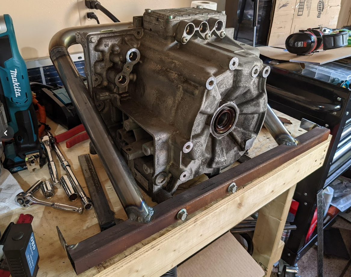
The transaxle core was re-scanned and imported into the blender model to mock up the sub-frame design. The sub-frame uses a steel tube construction and mounts to the frame rails in four locations.
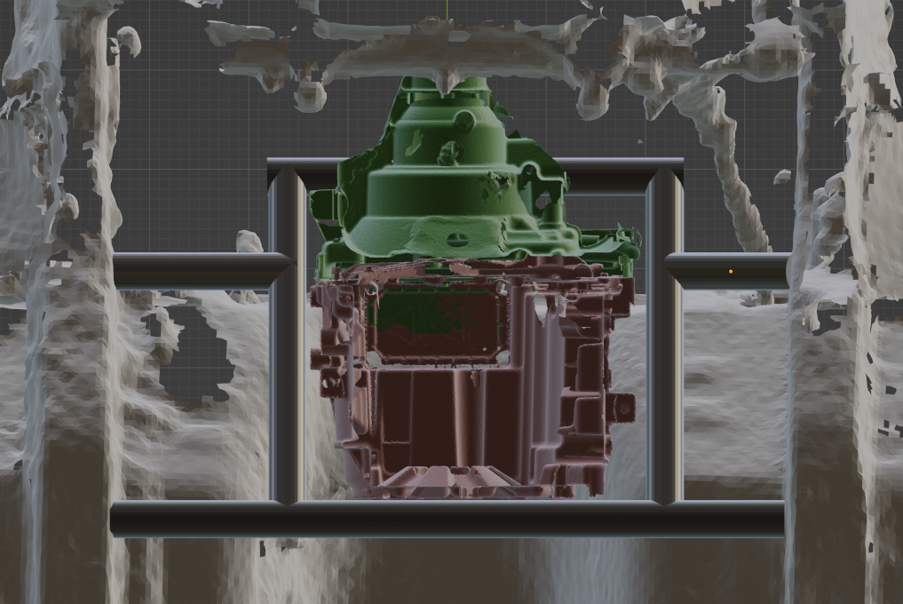
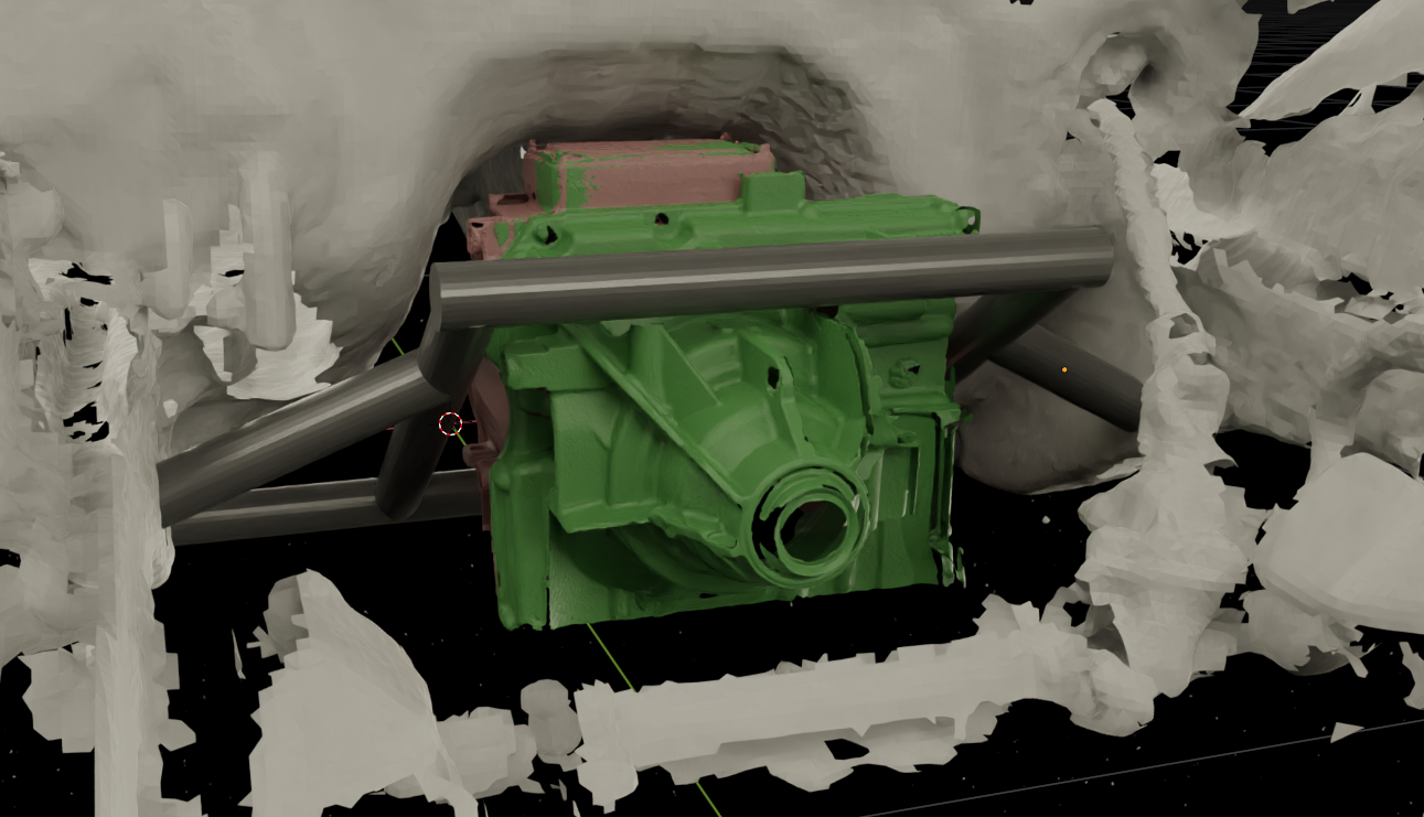
After verifying that there were no collisions with the power electronics model, measurements were taken from the Blender model of the sub-frame and used for fabrication.
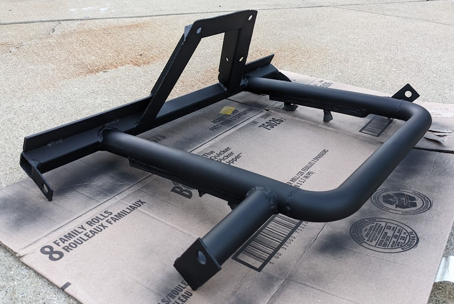
Main Sub-frame Fabrication
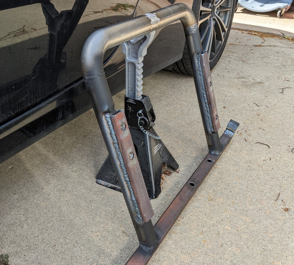
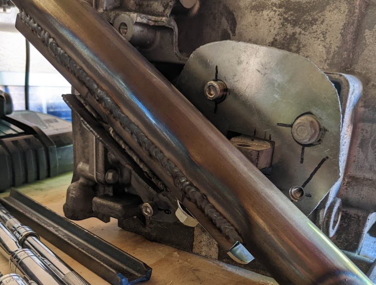
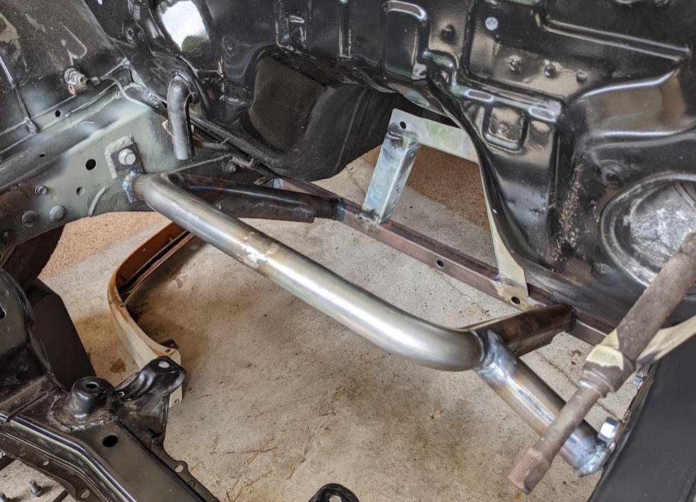
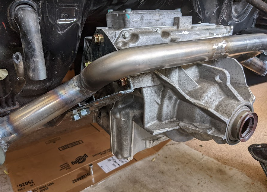
Two mounting holes at the rear side of the motor are level with the lower cross member of the sub-frame, so 1" square tube was used for the lower cross member. 1.5" round tube was used for the side pieces, and some leftover stainless steel tubing was used for the upper member.
A piece of 1" square tube was cut in half to create two U-shaped channels. Two class 10.9 equivalent M12 nuts were welded to the inside of each channel, and then the channels were welded to the side pieces. Some primer was sprayed onto the insides of the channel and on the round tube before welding to minimize corrosion in this hard-to-reach areas, but most of the paint ended up evaporating. Fluid Film will be used to coat the areas without paint after final assembly.
Motor Brackets
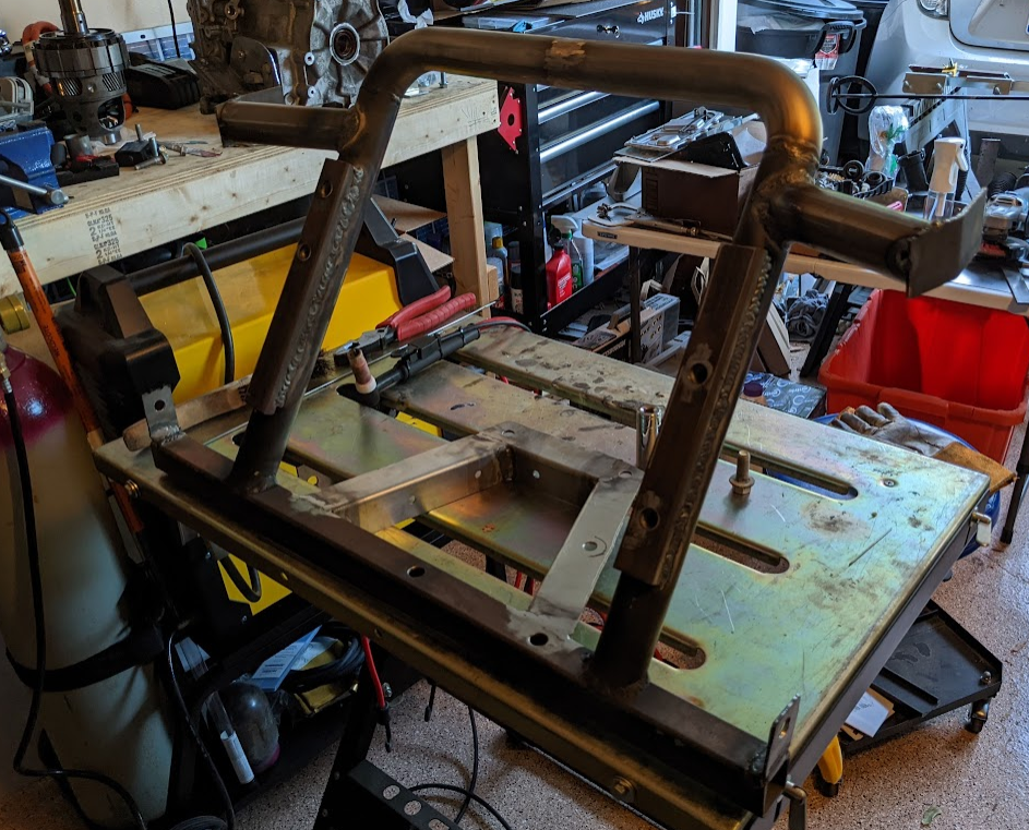
While the rear of the motor is bolted directly to the sub-frame, the sides of the motor are fastened to brackets, which bolt to the sub-frame from below.
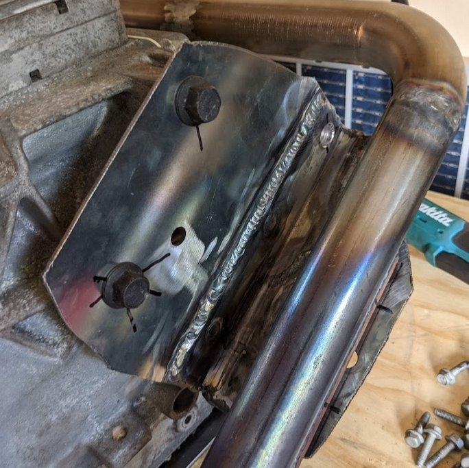
The right side bracket consists of multiple layers of sheet steel for added rigidity. The bracket is not yet reinforced enough to prevent it from flexing.
The left side bracket is secured to the motor with four M8 bolts. The center points for the bolt holes were located by looking at the threaded standoffs from various angles that are all perpendicular to the bolt direction, then blindly drawing a line with a permanent marker such that the marker always stayed in the center of the standoff from the current view perspective.
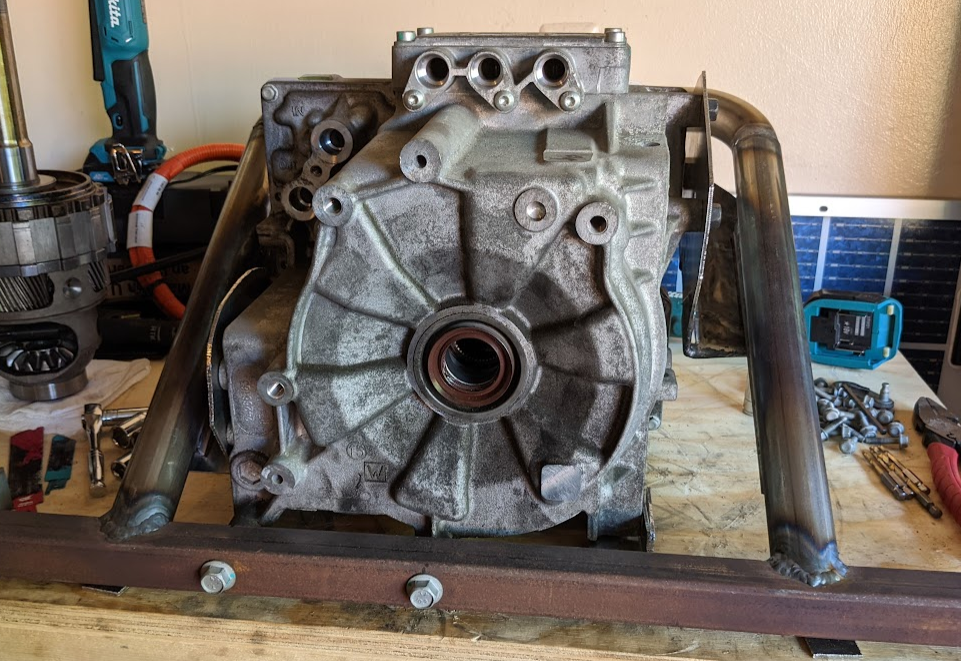
The sub-frame and brackets were fitted to the motor on the bench.
Additional pieces of bent sheet steel were added to directly connect the remaining rear motor bolts to the subframe.
Sub-frame Chassis Mounts
Mounting the sub-frame to the chassis was challenging. This was partially due to having to constantly shuffle in and out from underneath the car with the large sub-frame.
Additional round tube was added to mount the front of the motor sub-frame to the chassis. Some bent pieces of sheet steel were tacked in place at the end of the tubes to provide fastening points.
More M12 nuts were welded to the back of steel plates, and the plates were welded to the frame rails on both sides of the car. The brackets that were tacked in place on the bench were close, but not quite aligned to the steel plates.
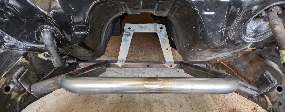
The brackets at the end of the steel tubes were removed, bolted to the frame rails, then re-tacked in place before being fully welded.
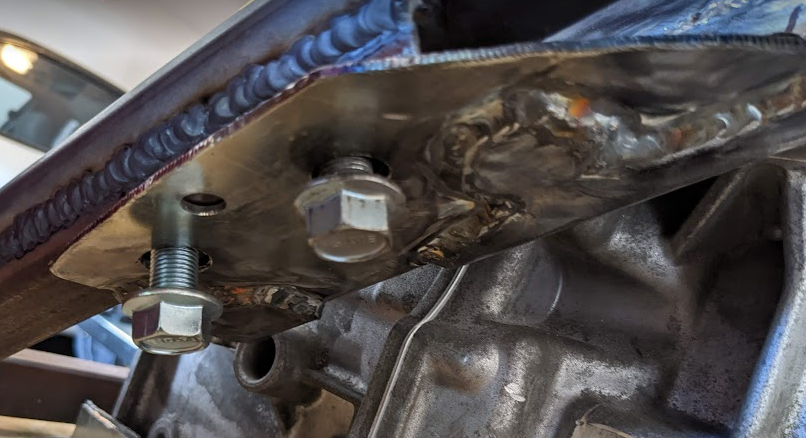
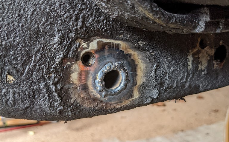
The lower chassis mount is designed to bolt straight through the frame rails using 100mm long class 10.9 M10 bolts with class 10.9 equivalent nuts. To prevent these fasteners from compressing the frame rails, a steel tube is welded through both frame rails. Welding these tubes through the frame rails was the most challenging part of designing the motor sub-frame. The frame rails are constructed from multiple thick sheets of steel which are spot welded together. When welding to the outer-most layer, the air expands between layers and causes the weld pool to explode outwards. These molten metal explosions burned through clothing and constantly gobbed up the tungsten. Most of the time spent on this welding process was shuffling out from under the car to the grinder to re-sharpen the tungsten.
Eventually, the job was completed and the sub-frame was fully mounted to the chassis.
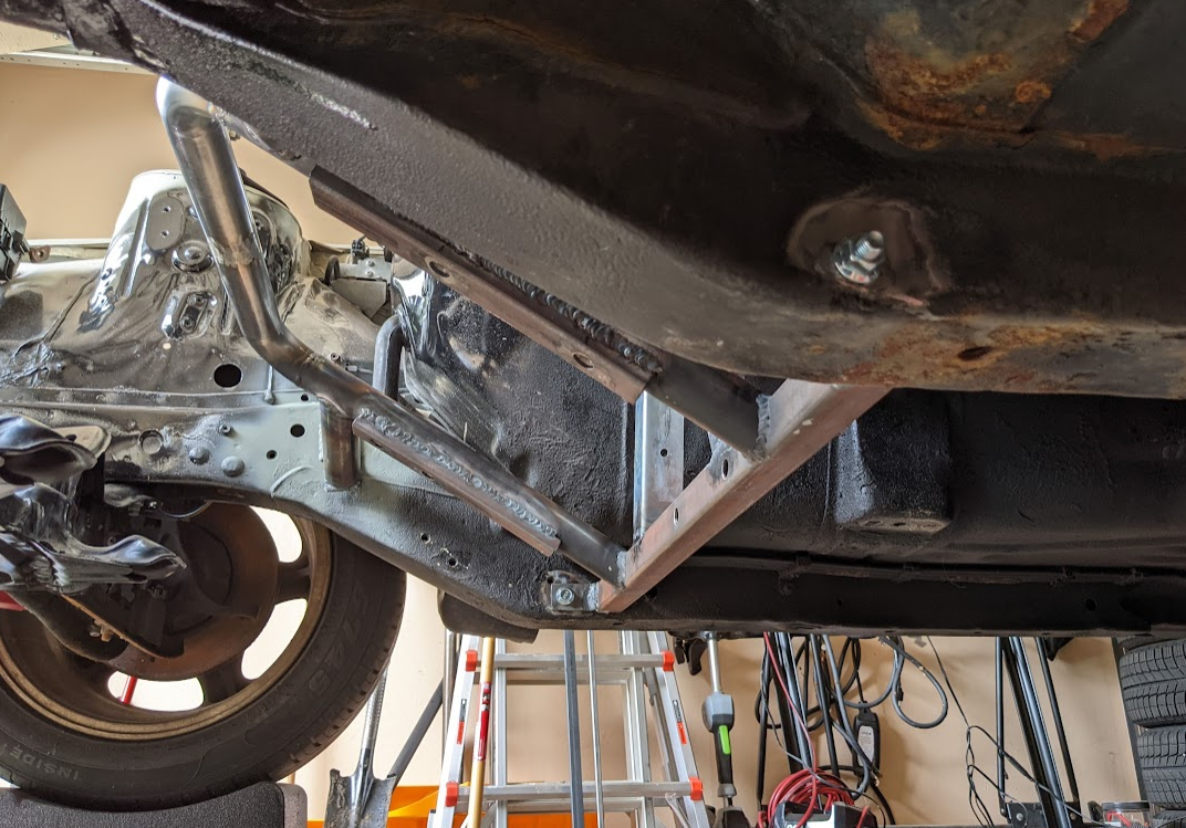
The left side of the car was subjected to a few brake fluid leaks and extra heat from the exhaust. Because of this, there is a lot more surface rust along the left side of the chassis, whereas there is virtually no rust on the right side.
Motor Fitment
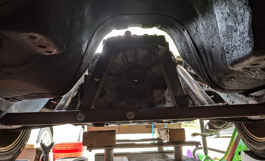
The motor is lifted into position from underneath the car using a motorcycle jack. Once close to being in position, the motor brackets are fastened to the sub-frame from underneath, then the five rear bolts are installed.
There is ample clearance around the motor for hoses and wiring.
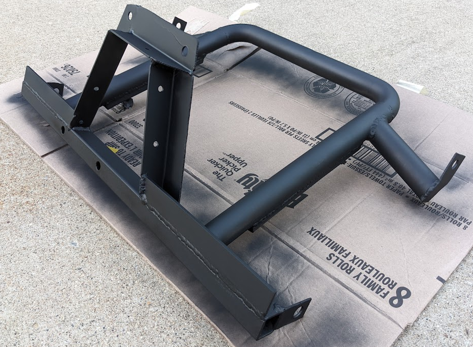
Sub-frame Reinforcement
Reinforcements were added to the 1" square tube to minimize sagging or bending under load, then the subframe was primed to prevent rusting as the project progresses. All components will be removed and properly painted once all the mechanical assemblies are fully completed.